The Galactic Senate Part 6: Creating The Floor.

So with the creation of the floor it was planned as follows: I want to make the floor itself, a hole in the floor, some triangles that seperate and open up the floor so people can go to and from the chancellors holding office, and I wanted to add the tunnels which yoda escaped from to just add a little flared detail (I added doors to these, they are too small for a character to actually go through they are intended to just be a nice detail). It is of note I planned the chamber itself to be approximately half the size of the actual studio model, this is to accomodate battlefront 2’s poly limits.

first I actually started the floor by duplicating the very bottom rows wall, I then duplicated the bottom edges and translated them down and scaled them in to make a taper. This will be the very start of my floor.

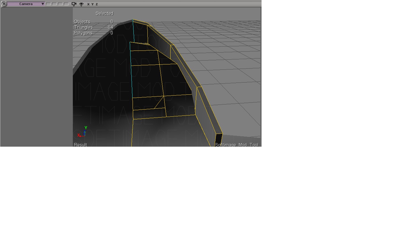
I repeated the duplication translation and scaling process with the edges selected until I had roughly this shape.

next around the base of the taper, I applied a basic texture and then plugged in the bump map into the diffuse and used render map to finish my texture (you can read about this process in part 3 and 4 of making the senate if you missed it)

for the next part of the taper I applied a slightly lighter texture, this will actually be the ledge a series of spot lights will rest on later.

next out of the next section of the taper down, I deleted some polygons, this will be where a yellow light bar goes. The deleted polygons will house some holo panels and some cylindrical stands, so the polys are not needed there.

I then installed the light bar texture onto the remaining polygons.

next for the very bottom of the floor I simply made sure the edges in the middle of both sections of the floor were approximately halfway between the two sections of the floor. this is more for texturing later than anything.

and finally I installed a very basic texture for how I thing the floor should look.

and as usual, I installed a bump map to the diffuse then rendermapped my texture to bake the final product.

next I added a cube for the base of that cylindrical stand (im not really sure what those things are somebody tell me if they know)

I then added a cylinder itself to that part, duplicated all the top faces, and scaled them down, I then translated them down to give this nice interior dip shape.

I then took the poly on the back, duplicated it and translated it backwards until I had a little bit of a tail sticking out.

with the modelling complete I applied a very basic texture to the model.

next for the creation of the holo panels base I simply added a cube, and duplicated its faces until I had 3 relatively even subidivisions I ran along the side of the wall where i deleted my polys earlier. I then drew some edges to create a bit of a rounded edge near the top.

I then added and baked a texture to resemble what this area looks like.

for yodas tunnel area I simply dragged a new cube and duplicated the sides, scaled them up and translated them sideways to make roughly 5 new rectangles. I then took the from face on both sides, and duplicated them scaled them down then dragged them to get that nice dip shape.

finally I created a cylinder for the tunnel itself, duplicated its top face and scaled it down and inwards to make that pipe like shape. I then selected the cube and went model > polymsh > boolean > union to merge both objects together.

after applying and baking a basic texture this is how we are looking for that area.

for the hole in the floor I created a triangle and duplicated it, rotated it by 20 degrees and continued this process until I had this nice shape with a hole in the middle ( the hole is left to create a godray in the chancellors holding office later)

for the lights on the floor I simply created cubes and adjusted them until they had a tapered shape, I then duplicated and rotated them across the rest of the floor, note I have a basic grey scale texture on them for now so i can see roughly how they will look before i finalize the textures.

I repeated the process of creating tapered cubes and applied the appropriate greyscale to the second row, duplicated and rotated them into position.

and once all the lights in row 2 were in place this is how my total floor was looking.

finally repeating this process for the final row I applied a nice reddish purple texture to the cubes and applied my appropriate bump map, then simply baked the texture.

Next I placed a series of spot lights facing towards the floor starting from each of those floor lights I used render preview to make sure all the lights looked proper.

with the lights aroung the outer ring after baking the texture with the lights this is how we looked.

and finally after baking the floor spot lights to the floor using render map, exporting the msh and getting it in game, this is how we are looking with the finished floor. Next we will be on to designing the chancellors holding office.

If you enjoyed reading this article and would like to help contribute to and support the blog and my projects you can click this text to leave a small donation.

The Galactic Senate Part 5: Rows And Lighting.

So in this section we are going to be making a few rows, and the first section of our rows the goal is to make so we can create and bake a basic light and shadow map, apply it to our current models and make it tilable so the rest of the senate can be made with just some simple duplication.

so first I started by duplicating the wall I made in the last part and rotated it 20 degrees then lined up the bottom of the wall with the bottom of the first wall.

I repeated that same duplication process until I had a complete ring of walls.

I then used the weld point tool and welded the sides of the wall together (I chose to weld to right side to the left sides)

next after the entire wall was complete I duplicated the base I created in the last part.

I simply repeated the same process as above, rotated each base by 20 degrees until I had all them added to the ring.

and finally I did the same thing with the pods. we actually dont need all of these pods for the shadow and lighting map, but I duplicated them to make sure my ring looked proper before I started (this way im not moving around polys last minute).

next I repeated this duplication process for the next two rows, However I only left 3 pods in the second row and 2 in the third row. The Middle pod of the second row is our template for our light and shadow map. when we bake our texture itll fake the lighting to the rest of the pods.

first I installed this cylindrical shape behind the pod this will be the light bar behind the pod.

and then I put this above the door to mark the red light in the centre of the door.

I created a single spot light in the scene and placed it 60 units above all the pods, then adjusted its cone until all the pods were hit evenly by its light. I then turned on its shadows, and adjusted its shadow map values until I had these nice soft shadows under the pods.

this is another rendered veiw of what the soft shadows look like inside the pod.

next for the lights behind the pod I placed a spot light and softened its intensity until I got what I thought the light should look like.

finally I repeated the spot light process for the middle light on the door. I removed my original spot light to show how the lights look.

Finally with all that in place I baked my shadow map. First to do this I simply change every object in the scene to have a plain white texture. Then I go Render > propertie > render map and simply bake my surface colors, this gives me my texture for my detail map (I used render type 28 (normal map with gloss) and in texture slot 2 I placed the shadow map to give soft shadows to the objects via texture) for the lights itself with shadows disabled I simply rendered another render map with the regular texture and surface color and illumination.

with our soft shadows and light map in game this is how the pods look.

With our pods and walls now tilable and just needing to be placed its time to move onto designing the floor.

If you enjoyed reading this and would like to help out and contribute to the blog and my future projects you can click this text to leave a donation.

The Galactic Senate: Part 4 Pod Housing Base And Wall.

So first initially this project was started with the intention of being a single model, however due to request I will be making this into a full senate map. Continue following this blog to see all the behind the scenes of how the entire map is being made. A lot of the techniques i’m using to create the rest of the map I covered in making the pod itself however I will still show roughly how i’m making each model.

so first for the base housing of the pod, I created a very tiny cube. This Cube I then lined up roughly where the housing will meet the back of the pod.

extending the cube out to approximately the desired length of the pod to where I want the door frame for the wall. (this will be adjusted later its just to give a bit of a visual while I model.)

next I extended the side face of the cube to be a little past where the side cylinder of the pod is.

and finally I translated the bottom face of the cube to be just below where the side cylinder of the pod is. This gave me roughly the shape of the top of the housing.

next I put two slices into the bottom face of my cube this is so I can extend a angle out of it later.

I actually screwed up so i deleted one of the slices and simply dragged the other one until I had roughly this shape.

finally I duplicated that bottom face and translated it both down and forward until it had approximately the angle im looking for.

I drew one edge at the bottom of this angle so I could create the middle.

then simply duplicated it and moved it until its position was 0 along the x axis. I then deleted the poly face where it wasnt needed (when this welds we dont want artifacts inside the model)

next I created a grid and placed it behind this shape roughly where i would want my wall (this was created more or less for a guide so I knew everything was lining up)

next I placed a new cube underneath the pod, this will be the place where the pod rests.

I then duplicated the bottom face, translated and rotated it until this nice curve was put into the cube.

I repeated this process one more time until this sort of cubic torus shape was made.

going back to the front of the model I duplicated the front face and scaled it down til I had this smaller rectangle on the inside.

I then duplicated it again and translated it backwards to make this rectangular indent.

duplicating the entire base so face I starting working on a high res model to bake my normals. I started by adding a few new edges to get two more rectangular boxes on the top face.

after translating and scaling them I wanted these two desired shapes.

next I drew more edges around where my pod would be sitting (I selected the polys im adjusting the help visualize where im going)

and again I simply duplicated them, scaled them down and translated them inwards to make this nice indent.

and finally the same process, I drew more edges on this side of my base, translated scaled them inwards until I had my full desired shape.

after completing this process this is roughly how my high res base looked for the pod (notice I hid the pod in this screenshot)

next for the high res stand portion i simply slice the polygon vertically until I had a number of subdivisions.

I then simply dragged the subdivisions up to make this nice curved shape with the two lanes in the middle.

then sliced these sections in the middle a number of times so I could make grooves later on.

after duplicating and dragging each of these sections this was the approximate shape i was left with on my high res model

finally I applied this really basic texture to the standard model and baked the normals with my high resolution model.

I then applied my normal map to the model, and one the texture and the newly baked normal map were on I checked to make sure it all looked right in my render preview.

Once I had my render where I wanted it I simply baked a rendermap to finish my texture.

and finally after making the base symmetric this was how we looked with the newly baked texture.

for the back wall I first duplicated the base so i could make sure I knew roughly where I needed the wall to curve (remember this will be a cylindrical taper of a room)

and the back grid I used as a template earlier I simply dragged the edge to the bottom of the bases angle.

I then drew a few edges around where I want the walls door to be (note this is going to be a temporary thing for now, once I figure out how my finished halls will be designed the door and textures will change)

I then duplicated this polygon and dragged it backwards to create the hall and door.

next for the high res door I started by seperating the door into the segments I want with different shades.

and i drew a bunch of edges for around where I want my high resolution door frame itself.

finally after the different segments were in and all my edges were drawn I dragged and scaled all my desired poly faces to make my grooves.

within edge I applied the texture I want to use to bake my high res normal map.

after applying all my new edges and translating all my surfaces this was what my back wall looked like for the high resolution model.

after baking the textures and the normal maps for both the walls and the base this is what we look like in game.

Now with the base and wall complete and ingame our next task will to be to start to duplicated some of the pods, bases and walls into rows so we can create a proper lighting and shadow map. This will be covered in our next part.

If you enjoyed reading this and wish to help support this project and future project within this blog, you can click this text to donate to the blog.

Behind The Scenes: Making Max Rebo.

Harrisonfog approached me with a fun idea for Jabbas palace in his remastered project, make Max Rebo to fit inside of the organ. The concept I was given was to make Max Rebo with his hands covering his face like he does in ROTJ.

So first I had to import our current model of the organ from SWBF2.

I placed a cylinder primitive inside of the organ. This will be where Max Rebo’s body starts.

Next I selected all of the polygon faces on the top side of the cylinder, duplicated them (ctrl+d) and translated them up, I then scaled them up to give this taper shape.

repeating that process of scaling, translating and duplicating only the top polygons of the cylinder, I did this 3 more times until I had this nice plump round ball like shape. This will be the base of his body.

The very top I scaled inwards a little more than the rest of the body, this is to eventually help the head and shoulder blend onto the body.

I created a cube primitive and positions it roughly to where I want the top of the head to be.

Next I simply duplicated and translated the back face of this cube along the Z and Y axis until I got this little curved shape (note at the very end of this I also dragged one of the edges to make a flat face 90 degrees from where I started.

after creating that 90 degree turn I continued to duplicated and translate until I had this nice tail shape for the back of the head

I then duplicated the side faces and translated them along the X axis to make 5 subdivisions, this will be used later to smooth out the back of this little head tail.

I dragged the points on the bottom of this shape to make roughly a cylinder like shape to help make the back of the head be more spherical by the end. this will be where that tail ends and meets the back.

next I dragged the very back faces of the polygons to be inside of the back.

I then selected the points of the polygons at the back of the tail and started translating them to create a smooth surface for the tail

repeating these steps I moved up the back of this polymesh and rounding the back until I felt it blended right.

I continued the smoothing process until I hit about this point, I want to leave this area as is for now so I can add the ears later.

next, similar to how I designed the back of the head, I duplicated and translated the faces on the front side of the cube to make approximately the shape of the forhead.

much similar to how the back of the head was designed I selected the points on the top of the forehead and began translating them until I got roughly a smooth surface for the forehead.

Once the forehead was smoothed I created a new cylinder primitive and placed it roughly where i think the arm should meet the bodys mesh.

I selected the side face of the cylinder, duplicated and translated it along the X axis several times until I got this shape on my cylinder. A break down of how this works is basically I create one set of subdivisions for the shoulder, two for the elbow, two for the hand and an extra set for where the fingers will meet.

Next I selected the points of the shoulder and dragged them inside of the bodys mesh to help visualize where the arm will meet the body.

I then scaled down the points where the elbow will be to help visualize where the arm will taper.

next same concept I scaled down the points for the hand to help visualize what the taper of the hand will look like.

Now with those tapers in place I simply have to take the other edges and points in the arm and translate them until my tapers blend with the arm.

next I created a new cylinder and selected its top face and duplicated it, translated it out, this will be a finger.

after creating the shape i wanted for the first finger I simply duplicated the finger model, translated, scaled and rotated it until I made the rough shape of the other 4 fingers.

with all the fingers in place I simply merged the 6 models together (arm and 5 fingers) this is so after I freeze the operator stack I can start welding the fingers to the arms.

After the fingers points where welded to the arms points you can see we are left with a much smoother shape.

with the arm complete I went back to the head and began dragging the 3 polygon faces on the bottom of where we left off with the forehead to make the trunk.

With this shape I began to first manipulate the points where the forehead ends to make a taper shape to the trunk.

Next I simply smoothed the polygons on the trunk to create a cylindrical shape.

then with the very bottom of the trunk I duplicated the bottom face of the trunk translated and scaled it down until I got this nice rounded bottom.

finally I selected all of the polygons in the middle of the trunk and scaled them down to give me a nice tapered appearance.

next for the ears I selected the polygons on the side of the head duplicated them and translated them out along the x axis.

I repeated this process 3 more times until i had the desired subdivisions for the ear.

next I simply selected the points on the outer edges of the ear and translated them along the X and Z axis until I had the approximate desired shape of the ear.

I then moves all the outer points closer together to make the outer edge of the ear thinner. I then started to drag each point until I had a nice smooth surface for the ears shape.

repeating these steps I created the other ear on the other side of the head. I then selected every poly on the “inside” of the model and deleted them (this is so i can properly weld the neck together)

to seal and create the remainder of the head and neck i simply selected the edges show above and dulpicated them and translated them to create more subdivisions.

with those subdivisions in place i simply welded the points from my newly created subdivisions to the top of the head.

repeating that with my remaining edges i created additional subdivisions for the neck and simply welded the points all together until my entire head model was one mesh.

Next i went back to the body model and used the add edge tool (default “\” key) to add edges around the neck pretty close to the head model but wasnt too worried about it being precise.

I then selected all the polygons inside those lines and deleted them to create this hole in my model (note what im about too do can be achieve through boolean union, but it doesnt always work so i like to do it manually on complex geometries)

I repeated this process around where the arms meet the body as well to create arm holes.

Next i simply merged my head, body and arm models into one mesh then started welding all the arm hole points to the arms and all the neck and head points to the head until the entire model was sealed.

and with all the points welding the model is complete. Now we want the arms to cover the eyes.

to accomplish this first i created a series of nulls as bones and set them as children of one another. I created seperate parent chains for the ears and arms.

As pictured here you can see the green lines are the nulls where my bones are placed.

next I simply enveloped my mesh to the bone nulls and prepared to turn some bones.

now I simply rotated and translate the bones (note i made an arm, forearm and hand bone) and moved the hands until they covered the eyes.

I then repeated this process with th other arm and hand until they were approximately where desired.

and finally i rotated the ears down until they rested on the shoulders.

finally with the model roughly where i want it to be I went edit > operator > freeze operator stack. this freezes the geometry in its current position and removes the envelope from the bones.

I duplicated the entire model after it was done to create a hi res model. at the back of the head i drew some edges with the add edge tool and translated their points outward to create some ridges.

on the fingers i simply created a greyscale bumpmap and applied it to the ip of the hi res models fingers.

for each of the fingers i drew an additional greyscale bumpmap to raise the details in the ridges of the fingers.

after all my fingers were in place i simply checked the render preview window to make sure my bump map looked alright.

I repeated this process and simply added some spots to the remainder of the hires model. After I was satisfied with this I simply opened ultimapper in XSI selected my hires model as my source and started baking a normal map and an ambient occlusion map.

after that was baked I simply chose a plain blue texture and applied my new normal map to the model in XSI. against that plain blue texture this is what it looked like. When complete I went into XSI Rendermap and rendered a new diffuse.

And with my new diffuse I created a material, and applied it to the model, I used render type 28, in texture 1 i put my newly baked normal, with texture 2 i put my AO map (darkned by 50%), exported and ingame, and this is how we look. I know the texturing section seems short but thats all there was too it, I made a blank texture with only blue, applied some normal maps, and let xsi do the rest. And thats it we have our new model :).

You can help support the blog and my projects by clicking this text to donate.

The Making Of Repulsor Pod: Part 2 Modelling High Resolution

So before we begin lets understand what our High Res model actually is. It is important to understand that High Resolution DOES NOT MEAN it is going to be a movie quality model, it is basically a higher quality model and by the end it will be compressed into a texture (normal map) that will display approximately where we want our texture to displace light. As an example if we had a polygon raised directly above another polygon you wont be able to tell that it has depth once its compressed, what we want to do is slightly taper our raised edges so when it compresses we get almost a bevelling effect.

I started out high resolution model the same way I started the other model, with a cylinder in the exact same place, then I selected all the top poly faces, duplicated them and scaled them down, then I raised them and repeated until I got the shape above prefectly lined up with our standard resolution model.

I then duplicated the top faces again scaled them down more to create the edge of the pod and then duplicated them again and moved them down along the Y axis to create the middle and floor of the pod.

I raised the back polys and welded the points together the exact same way I did for the standard resolution pod to make that back triangular section. then I selected all the polygons on the back of the pod and went to Model > Polymesh > slice polygons, to create an even number of edges to deform and smooth the pod. (notice my settings sliced along the Y axis, with 2 slices and 33% spacing between them to make it almost perfectly split into 3 poly faces.

I repeated the above process for the polygons along the side of the pod until I had roughly even spacing between my new poly faces and enough new edges that I could make a smooth surface out of the outside of the pod.

I began selecting those newly created edges and scaling them up (or down) to create a rounded surface, everything you see in the shape was done only with scaling (no translating was needed)

After I was comfortable with the shape of the outside of the Pod, I went to Model > Poly. Mesh > add edge tool and added edges at the front of the model to make the section where that weird black wavy strip on the pod is.

After I felt I had enough edges I simply selected the polygon faces I wanted to move inwards with the raycast polygon tool, and duplicated them. I then scaled them to be smaller along the X, Y and Z axis to move them inwards while also leaving a small bevel look on the inside so our normal map deforms the light more prominently.

Next I modelled and scaled the seats the exact same way as I did with the standard resolution model, and scaled them to exactly match the position of the standard model. I then added a few extra edges using the add edge tool for where I wanted the seat cushions to go upward.

I then duplicated the poly faces I wanted to use for the cushions and scaled them down to give a more rounded appearance. I added new edges to give a sort of “paddle” shape to the middle of each cushion for a butt groove, then duplicated those faces, scaled them down and then translated them down until I was happy with their shape. I repeated this process another two times for the remaining cushions.

Here you can see our completed cushions.

Next for the back panels in between the seats and the bottom of the seats I simply used the slice polygon tool, sliced each panel into 14 equal pieces, and then selected every second polygon face, so I could get those nice grooves and gaps. Once selected I simply scaled the up to give the nice indented look you see above.

Using the same steps above, I sliced the polygons on the other side of the seats to make the pods inner lights, duplicated every second face and scaled them up to create more indents.

flipping around to the bottom side of the pod, I did the bottom the exact same way I modeled the standard resolution, but I made the sphre on the bottom with an extra set of polygons. I then selected the circle around them and selected my polygons in a Y shape, duplicated them and translated them down along the Y axis to create the bottom of the pod (we only really see this in the movie when palpatine and yoda play dodge ball.

Finally for the plastic in the middle I just used a cylinder texture projection on that one small part of the outer pod and went render > texture > image and selected a greyscale of the image.


At the bottom of the texture properties pop up that comes up when you assign your image I simply used the check box to enable bump mapping and set the factor to 10 (this will make it so when we start baking our normal map the bumpmap will be baked as well).

Finally with the STANDARD RESOLUTION model selected I went into Render > Property > Ultimapper.

Inside ultimapper I set my path (where I want the images to be exported to). I then set my high resolution source and picked the model I made in this section. Set my type to targa, my resolution to 1024, quality to highest, and checked the boxed for ambient occlusion, depth and normal in tangent space. (normal in tangent space will give us our baked normal map. Depth map is not needed but I use it as a guide when im making my textures, Ambient Occlusion I use to make my textures in XSI). After selecting my settings I simply clicked computer so XSI knows how far we are from the low res surface and then clicked generate at the top to make my maps.

Using my depth map as a stencil I created this really crappy looking texture, I just wanted to basically get the colors we needed for the model in this, It did not have to be shaded or fancy by any means as XSI will do the work for us.

Next inside of my material settings (I named my material GSC_POD_1 and simply clicked edit inside the XSIZETOOLS manage materials section) I clicked on the little grey plug icon to the left of where it says AMBIENT and clicked Blend With > Image and selected my newly baked AMBOCC (ambient occlusion). I also clicked the Diffuse plug (the red one) and at the bottom enabled bump mapping, next to where it says Factor on the bump map I clicked the plug and selected a greyscale copy of the normal map we just baked. After selecting that image I clicked bump on that images properties as well and kept the scale at 5. (This is so render map will export more depth in our texture.

Finally I went Render > Properties > Rendermap, set my format X resolution to my textures resolution (1024), set super sampling to 2, selected my standard resolution pods texture projection, set my format to .TGA, set my export file path and then simply clicked Regenerate.

After clicking regenerate this is what XSI made out of our old boring flat texture. after adding ambocc and some bum mapping.

And of course how our texture looks when applied to the standard resolution model.

I created a new material for the pod and assigned it to the pod (to save time on unplugging all the textures we used) I made it render type 28 (bump/specular) copied my normal map to my mod folder, and named it cgs_pod_diffuse_1_bump.tga and set that as texture1 in my ZE flags.

Finally with part 1 of our outer pod finished I exported and placed it in game.

And how the outside of our pod looks in game.

That wraps up this section, in part 3 we will be finishing the high resolution of the cylinders on the sides of the pods, we will also model the high res and textures for the pods consoles.

Enjoyed reading the making of this model? You can make a donation by clicking this text to support the blog.

Behind The Scenes: To Fix a Wookiee

While working on Harrisonfogs Battlefront II Remaster Project a problem arose with our standard Wookiee. The vanilla mesh really deforms around the neck, one of the assigned tasks was to fix this problem with the Wookiee, while maintaining a low poly count, here I will show you how I accomplished this.

As you can see here the wookiees face deforms very unnaturally

So first I started by duplicating the entire model, I then selected all polygons except for the polygons around the beard. We are going to delete all these polygons until just the beard remains.

With the beard now cut out we will eventually be making this into a cloth to give the illusion of moving hair.

Next back to the original model I started by using the Add Edge tool in XSI to draw edges around where I want the Jawline to be. (I used raycast polygon to highlight the polygons above where I drew the jawline).

Next I drew another set of lines directly parallel to that jawline, this will be the area that I round the edge of the jaw and blend it into the neck.

After I drew another set of lines parallel to the base of the neck / beard area, this will be where my neck connects to the head.

Finally I duplicated that model and selected all the polygons on the head. I want to delete this portion of the model to make sure the head and the body are kept apart to make sure the neck deformed properly.

I did the opposite to the other duplicate model that I had, I selected every poly face except the head pieces and deleted them to get my separate head mesh.

Next I selected all the points in the Second line I drew, the reason for this is that the first line marks our jawline, but the second line is where we want to smooth our jaw into the neck.

I scaled the points both along the X and Z axis until I was satisfied with the curvature it created, for the most part this will be hidden by hair so it didnt have to be perfect or high detailed.

I then selected the points at the end of the head, remember this will be where we blend the bottom of the neck to the jaw.

I scaled this section as well until I was satisfied with its location, it needs to still be semi flat to kind of resemble the bottom of a jaw but remain with enough width to hold the neck.

For the final part of the head model I adjusted the UV until it was at the bottom of the neck fur, as to prevent the model from appearing too stretched with its texture.

Now I made the original model visible again we can see the big hole that was left in the neck, we need to correct this.

I started by selecting all the points at the edge of that hole and scaling it down on the X and Z axis until it matched the coordinates at the base of the head model.

after I was satisfied with its location I selected the next ring of points.

I scaled those down until there was a slight upward curvature to resemble a neck.

Back to the beard portion of the model, I opened the weight editor and made sure the beard was weighted 100% to the head bone. (we don’t want any odd deforming around the neck)

Next because of how cloth works and deforms in battlefront we want to remove all triangles. So highlighted above is one of the edges I removed, I removed all similar edges until the beard was left with a series of quads.

After making the beard full of quads I went to XSIZEtools and applied its cloth function, set the texture for the cloth (all_inf_wookie.tga) and then picked my fixed points (they are highlighted red in the picture above)

I navigated to the odf folder for the wookiee and created a new odf file (all_inf_wookie_fur.odf) and filled it with the following text so the game knows that this is our cloth and that it is transparent (or uses a transparency flag) and that the transparency is hardedged.

I also had to open the all_inf_wookiee.odf and add the line for Clothodf so the game knows what to look for.

Finally I went into XSI explorer view and renamed the beard portion to be all_inf_wookie_fur, after the odf.

I created a brand new cylinder primitive also had to be made and applied to the cloth so the game knows the boundary of where the cloth should be.

And added the primitive to the collisions section of the cloth properties.

And thats it, after exporting and getting it in game we can see the odd deformation is gone and the wookiee’s beard has been fixed.

Like what you read on this blog? Click here to make a donation

The Making of Repulsor Pod: Part 1: Modelling Standard Resolution.

So first: I looked on google for what I was going to build (I won’t post pictures here, I literally google “Galactic Senate Pod” and just went off what I saw).

After looking at the pods, I came to the conclusion that they are relatively symmetric (both sides are the same dimensions) so for the duration of modelling I modelled in a way where I only had to modify one side of the model at a time.

First I started with a cylinder primitive since I’m going to be modifying it symmetrically I only need half the actual cylinder for this.

Next I cloned my cylinder by going into Edit > Duplicate/Instantiate > Clone Single. A clone is basically a duplicate copy of the object but any changes you make to the original object will also be changed in the clone. This is very useful for what we are doing so our clone can be used as a visual reference.

Next with the new cylinder I cloned I went to Model > Poly. Mesh > Symmetrize Polygons. This makes our clone symmetric and now as we modify our original cylinder, both sides of the clone will be modified. (note if you go into your explorer view (press the 8 key) and right click on the clone you can click Properties > and all the way at the bottom click the box that says “selectability” this makes your clone no longer selectable and really helps to modify the model so you don’t accidentally click on it.

So next on my original cylinder I used the raycast polygon tool (U key) and selected all of the faces on the top of the cylinder and translated them upwards on the Y axis until they were where I wanted them to be. This will eventually become our light bar at the bottom of the pod.

After, I duplicated the polygons (ctrl + d) and moved them up further on the Y axis and then scaled them to be smaller to make the outer edge of the pod become tapered.

Repeating the previous process I duplicated the poly faces again and raised them again on the Y axis, this time they were moved up slightly less to give the appearance that our taper is starting to become round at the top.

Next I duplicated all those faces but this time I did not raise it, this will be the flat edge of our pod (If you look at pictures of a senate pod there is a flat edge towards the front of the pod on either side). I scaled them just enough until I think they were where they should be.

Next I selected only the back polygons of the pod, duplicated them and raised them, This will be the triangular looking part at the back of out pod that houses the hand rail.

After I was comfortable with the position and height of the triangle, I simply went Model > Poly. Mesh > Weld Point Tool and welded all the top points towards the outside of the pod, to the top points toward the inside of the pod to make the Mesh triangular.

I then selected all the Polygons on the inside of the pod and duplicated them, and simply lowered them downwards to make the walls and floor on the inside of the pod.

Because of the way duplication works you will notice there are some unwanted polygons now on the inside of the pod, I simply selected them and deleted them. Now the pod had a completely empty floor with no divider.

I then turned my camera to the bottom side of the model and selected all the polygons, duplicated them and scaled them down to make a smaller circle under the pod.

After scaling them I translated them down slightly on the Y axis to give the bottom a small taper that will eventually be a kind of sphere / cone.

I then selected the single point in the middle of those polygons and translated it downwards along the Y axis to make the illusion that the mesh was more rounded.

Next back on the inside of the pod I selected the four polygons towards the back of the pod, these will eventually be the three seat on either side of the pod. I duplicated these polygons, and scaled them inwards slightly to make the ledge that the seats seem to sit on.

Next I went Model > Poly. Mesh > add point tool and added three points on the edges on the floor near the front of the seats. We will use these points later to weld the polys to the floor. I also selected the edges of the seats and dragged them slightly down on the Y axis to where the back of the seats should end.

Next I flipped my view port into depth cue and selected these not needed polys at the bottom of each seat and deleted them.

After those were deleted I went Model > poly. mesh > weld point tool and welded the three points I made earlier to the bottom of the chairs this allowed the chairs to be welded seamlessly to the floor.

Finally I selected the two poly faces at the bottom of the chair, duplicated them and scaled them, pulling them inwards until I was comfortable with where they landed. Remember this is only two poly faces that we are going to fit three seats on so we wanted them to have enough space.

Finally repeating the same process above of deleting polygons, creating new points and welding the points to the floor I welded the newly duplicated parts of the chair to the floor to make it seamless.

Next using the same steps I did at the beginning of this post, I created a cube and dragged it forward to the pod, cloned it, symmetrized it and made it not selectable so I could model only one side of the cube symmetrically.

As this cube will eventually be our control console for the pod I moved the top face poly’s of the cube upwards on the Y axis til it was at the desired height.

I then duplicated the back face of the cube and moved it backwards on the Z axis, and scaled it along the X axis, repeating this process twice until I had my desired shape for the console.

I then went into point selection mode and moved the points on the console down on the Y axis until I was comfortable with their position.

I then duplicated the polys on the top of the console and scaled them down slightly, then duplicated them again and translated them down along the Y axis to create the dip we want in the console.

After again deleting the poly’s in the middle of the console I duplicated all the top faces of the console and rotated them upwards to make the computer screen area we see.

I then scaled it down until I was given the shape that I wanted for the console.

Next I went Model > Poly. Mesh > Add Edge Tool and drew some edges around where the actual computer screen would be on our pod.

I then simply duplicated these Faces and pulled them outwards to make the computer screen.

Backing out on the complete model so far this is how we are looking:

Next I created a cylinder for the sides of the pod and dragged it into approximately where I thought it should go. I then selected all of it’s top faces and pulled them up along the Y axis and scaled them down slightly to make them round.

I then selected the point at the centre much like we did with the bottom of the pod, and translated it upwards to make it look slightly more round. I repeated both those steps a second time to also round the bottom of the pod.

Backing away to examine the finished pod model this is what we are looking at.

For the UV map I simply went Model > Property > Texture Projection > Unique UV’s (when prompted I selected individual polygon packing), I then manually selected and snapped all the points of the UVs I wanted together until I ended up with this section for the front of the pod.

Repeating that process of dragging the poly’s together and snapping them I put only the bottom faces of the UV map together until it looked like this.

Next I selected the inside walls and snapped those together, I chose to avoid the chairs because they are very different in texture from the walls, as there is a break between the walls and the chair I made the back poly its own seperate UV area and the front three poly’s to be their own map.

Next I made The UV for the floor, Since I wanted these to be fit in as small an area as possible I put the floors UV right above the Bottom of the Pods UV.

For the chair I connected all the points that would have “cushions” on them, while i kept the portions of the wall together, this is because the walls share the same rough texture but the cushions do not, and we want the lower wall portion of the seats to blend as seamless as possible.

After all our polys were dragged and snapped together this is how are UV map looked.

Next for the cylinders on the side of the model I used again a unique UV projection (we dont want cylinder projection since that really would make the tops and bottoms of the model look weird and we want it to blend seamlessly. I put the top and bottom section of the cylinder as its own UV and I made the sides their own,

Finally for the console I kept the sides as their own, I also seperated the top edge and inside into its own UV and the console and computer into their own space. I put this in the corner of a new set of image coordinated because this will use a different texture that is shared with the senate pods mount by the end. We will be modelling that a lot later.

Now with all our UV’s together that Concludes the section on Modelling the standard resolution model next we will be moving onto our high resolution model for our Normal Map (I do my textures in XSI so we will need that done before we design textures).

Like what you read here? Click here to make a donation.