So first: I looked on google for what I was going to build (I won’t post pictures here, I literally google “Galactic Senate Pod” and just went off what I saw).
After looking at the pods, I came to the conclusion that they are relatively symmetric (both sides are the same dimensions) so for the duration of modelling I modelled in a way where I only had to modify one side of the model at a time.
First I started with a cylinder primitive since I’m going to be modifying it symmetrically I only need half the actual cylinder for this.

Next I cloned my cylinder by going into Edit > Duplicate/Instantiate > Clone Single. A clone is basically a duplicate copy of the object but any changes you make to the original object will also be changed in the clone. This is very useful for what we are doing so our clone can be used as a visual reference.

Next with the new cylinder I cloned I went to Model > Poly. Mesh > Symmetrize Polygons. This makes our clone symmetric and now as we modify our original cylinder, both sides of the clone will be modified. (note if you go into your explorer view (press the 8 key) and right click on the clone you can click Properties > and all the way at the bottom click the box that says “selectability” this makes your clone no longer selectable and really helps to modify the model so you don’t accidentally click on it.

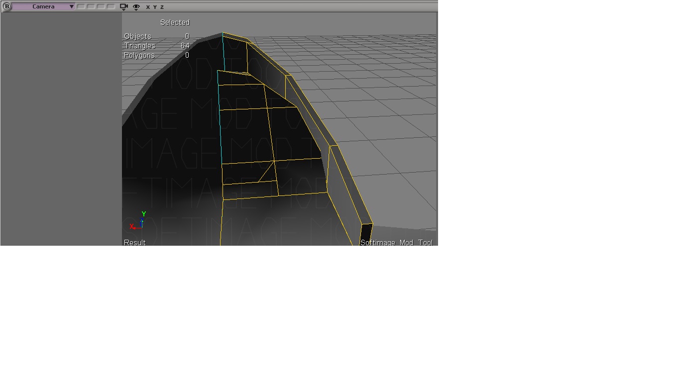
So next on my original cylinder I used the raycast polygon tool (U key) and selected all of the faces on the top of the cylinder and translated them upwards on the Y axis until they were where I wanted them to be. This will eventually become our light bar at the bottom of the pod.

After, I duplicated the polygons (ctrl + d) and moved them up further on the Y axis and then scaled them to be smaller to make the outer edge of the pod become tapered.

Repeating the previous process I duplicated the poly faces again and raised them again on the Y axis, this time they were moved up slightly less to give the appearance that our taper is starting to become round at the top.

Next I duplicated all those faces but this time I did not raise it, this will be the flat edge of our pod (If you look at pictures of a senate pod there is a flat edge towards the front of the pod on either side). I scaled them just enough until I think they were where they should be.

Next I selected only the back polygons of the pod, duplicated them and raised them, This will be the triangular looking part at the back of out pod that houses the hand rail.

After I was comfortable with the position and height of the triangle, I simply went Model > Poly. Mesh > Weld Point Tool and welded all the top points towards the outside of the pod, to the top points toward the inside of the pod to make the Mesh triangular.

I then selected all the Polygons on the inside of the pod and duplicated them, and simply lowered them downwards to make the walls and floor on the inside of the pod.

Because of the way duplication works you will notice there are some unwanted polygons now on the inside of the pod, I simply selected them and deleted them. Now the pod had a completely empty floor with no divider.

I then turned my camera to the bottom side of the model and selected all the polygons, duplicated them and scaled them down to make a smaller circle under the pod.

After scaling them I translated them down slightly on the Y axis to give the bottom a small taper that will eventually be a kind of sphere / cone.

I then selected the single point in the middle of those polygons and translated it downwards along the Y axis to make the illusion that the mesh was more rounded.

Next back on the inside of the pod I selected the four polygons towards the back of the pod, these will eventually be the three seat on either side of the pod. I duplicated these polygons, and scaled them inwards slightly to make the ledge that the seats seem to sit on.

Next I went Model > Poly. Mesh > add point tool and added three points on the edges on the floor near the front of the seats. We will use these points later to weld the polys to the floor. I also selected the edges of the seats and dragged them slightly down on the Y axis to where the back of the seats should end.

Next I flipped my view port into depth cue and selected these not needed polys at the bottom of each seat and deleted them.

After those were deleted I went Model > poly. mesh > weld point tool and welded the three points I made earlier to the bottom of the chairs this allowed the chairs to be welded seamlessly to the floor.

Finally I selected the two poly faces at the bottom of the chair, duplicated them and scaled them, pulling them inwards until I was comfortable with where they landed. Remember this is only two poly faces that we are going to fit three seats on so we wanted them to have enough space.

Finally repeating the same process above of deleting polygons, creating new points and welding the points to the floor I welded the newly duplicated parts of the chair to the floor to make it seamless.

Next using the same steps I did at the beginning of this post, I created a cube and dragged it forward to the pod, cloned it, symmetrized it and made it not selectable so I could model only one side of the cube symmetrically.

As this cube will eventually be our control console for the pod I moved the top face poly’s of the cube upwards on the Y axis til it was at the desired height.

I then duplicated the back face of the cube and moved it backwards on the Z axis, and scaled it along the X axis, repeating this process twice until I had my desired shape for the console.

I then went into point selection mode and moved the points on the console down on the Y axis until I was comfortable with their position.

I then duplicated the polys on the top of the console and scaled them down slightly, then duplicated them again and translated them down along the Y axis to create the dip we want in the console.

After again deleting the poly’s in the middle of the console I duplicated all the top faces of the console and rotated them upwards to make the computer screen area we see.

I then scaled it down until I was given the shape that I wanted for the console.

Next I went Model > Poly. Mesh > Add Edge Tool and drew some edges around where the actual computer screen would be on our pod.
I then simply duplicated these Faces and pulled them outwards to make the computer screen.

Backing out on the complete model so far this is how we are looking:

Next I created a cylinder for the sides of the pod and dragged it into approximately where I thought it should go. I then selected all of it’s top faces and pulled them up along the Y axis and scaled them down slightly to make them round.

I then selected the point at the centre much like we did with the bottom of the pod, and translated it upwards to make it look slightly more round. I repeated both those steps a second time to also round the bottom of the pod.

Backing away to examine the finished pod model this is what we are looking at.

For the UV map I simply went Model > Property > Texture Projection > Unique UV’s (when prompted I selected individual polygon packing), I then manually selected and snapped all the points of the UVs I wanted together until I ended up with this section for the front of the pod.

Repeating that process of dragging the poly’s together and snapping them I put only the bottom faces of the UV map together until it looked like this.

Next I selected the inside walls and snapped those together, I chose to avoid the chairs because they are very different in texture from the walls, as there is a break between the walls and the chair I made the back poly its own seperate UV area and the front three poly’s to be their own map.

Next I made The UV for the floor, Since I wanted these to be fit in as small an area as possible I put the floors UV right above the Bottom of the Pods UV.

For the chair I connected all the points that would have “cushions” on them, while i kept the portions of the wall together, this is because the walls share the same rough texture but the cushions do not, and we want the lower wall portion of the seats to blend as seamless as possible.

After all our polys were dragged and snapped together this is how are UV map looked.

Next for the cylinders on the side of the model I used again a unique UV projection (we dont want cylinder projection since that really would make the tops and bottoms of the model look weird and we want it to blend seamlessly. I put the top and bottom section of the cylinder as its own UV and I made the sides their own,

Finally for the console I kept the sides as their own, I also seperated the top edge and inside into its own UV and the console and computer into their own space. I put this in the corner of a new set of image coordinated because this will use a different texture that is shared with the senate pods mount by the end. We will be modelling that a lot later.

Now with all our UV’s together that Concludes the section on Modelling the standard resolution model next we will be moving onto our high resolution model for our Normal Map (I do my textures in XSI so we will need that done before we design textures).
